Summary
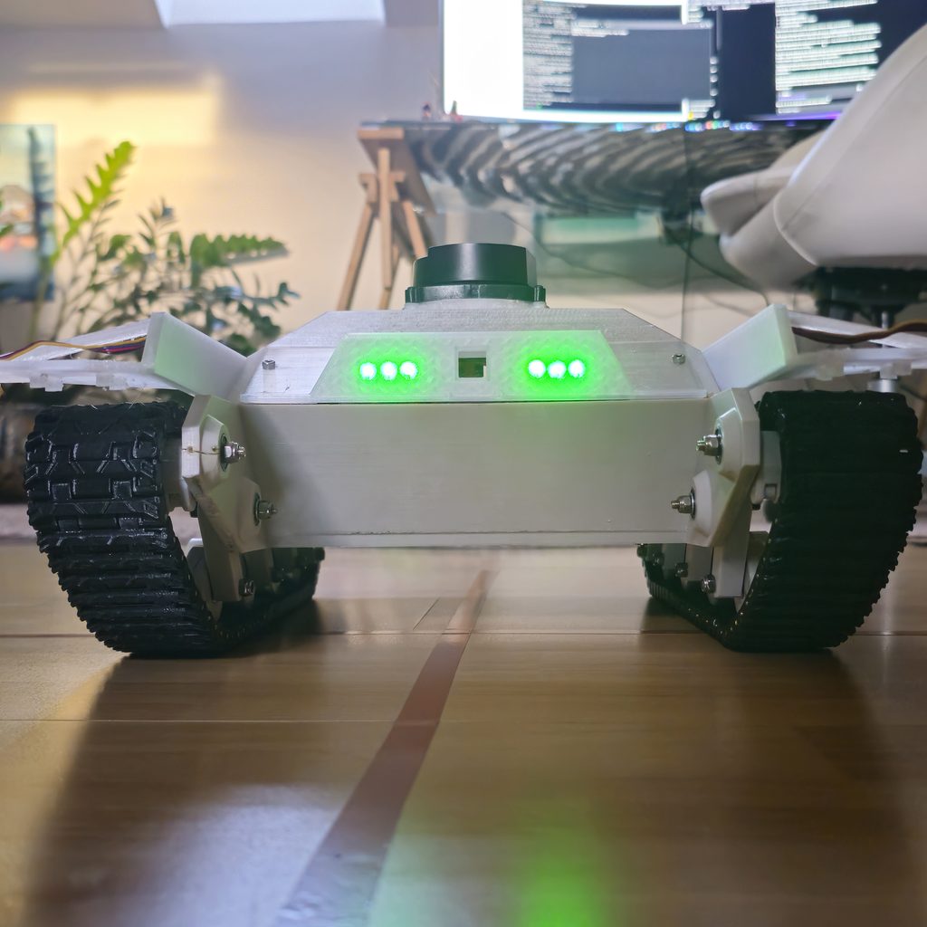
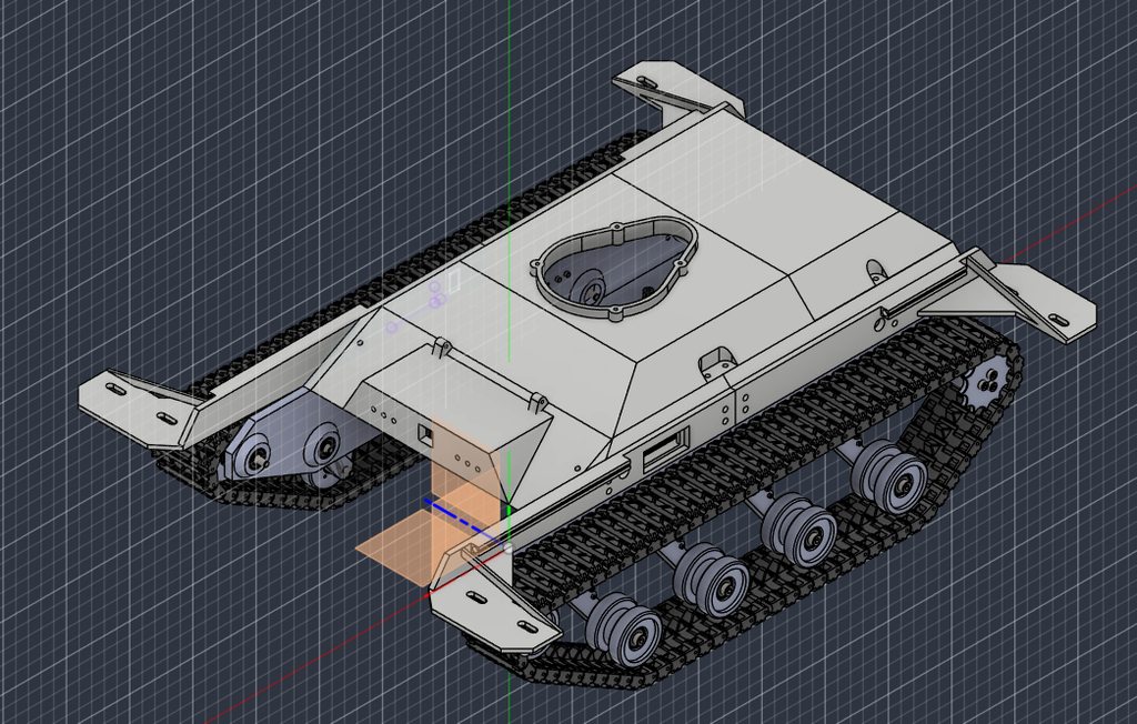
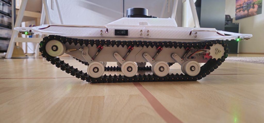
This crawler robot is based on the 3D Printed Tracked Robot Platform by Dejan Nedelkovski from How To Mechatronics.
The original mechanical design of the tracked chassis comes from his open maker project. My version is a personal hobby build based on this platform, with my own modifications and extensions in the areas of electronics, sensor integration, ROS 2, SLAM, motor control, odometry, and future autonomous navigation experiments.
The goal of this project is not to present a completely original robot design, but to learn by building: starting from an existing open design, adapting it to my own hardware, and gradually turning it into a small autonomous crawler robot.
GPIO Header Assignment
The Raspberry Pi 4B (4 GB) is fitted with a custom distribution board manufactured by PCBWay. The GPIO header assignment for this distribution board, including the additional connected signals, is documented here: GPIO Header Assignment.
Tracked Robot Kinematics
The ROS 2 cmd_vel (command velocity) topic is subscribed to by the velocity_target_node. A velocity command consists of two independent components: a linear velocity along the x-axis (linear.x) and an angular velocity around the z-axis (angular.z).
The combination (superposition) of these two components describes the desired motion of the robot, including straight-line movement, rotation in place, and driving along a curved path.
For a tracked vehicle such as the Crawler, these velocity commands must be converted into individual velocities for the left and right tracks. This conversion is based on differential-drive kinematics, taking into account the effective distance between the tracks.
The mathematical derivation and its implementation are explained in more detail on the Tracked Vehicle Kinematics page.
Hardware
The Crawler uses multiple sensors to estimate its motion, observe its surroundings, and detect potentially dangerous terrain.
Inertial Measurement Unit (IMU)
Hardware: SparkFun 9DoF IMU Breakout – ICM-20948 (Qwiic)
Interface: I²C
The inertial measurement unit provides acceleration and angular velocity measurements. Although the sensor supports nine degrees of freedom, the Crawler primarily uses its rotational measurements to estimate changes in orientation.
The IMU complements wheel odometry, particularly during rotational movements, when wheel slip or mechanical inaccuracies can introduce errors.
Wheel Odometry
Hardware: 2 × SparkFun TMAG5273 Mini Linear 3D Hall-Effect Sensor Breakout (SEN-23881)
Interface: I²C
Two magnetic Hall-effect sensors measure the rotation of the Crawler’s wheels.
The measured wheel rotations are used to calculate differential-drive odometry, providing estimates of both linear and angular movement.
Wheel odometry supplies the robot’s estimated forward velocity (linear.x), rotational velocity (angular.z), and relative position and orientation.
Since odometry errors accumulate over time, additional sensor measurements and SLAM are required to maintain an accurate estimate of the robot’s position.
Cliff Detection
Hardware:
- 4 × Adafruit VL53L4CD Time-of-Flight Distance Sensors (Product ID 5396)
- 1 × TCA9548A I²C Multiplexer
- 1 × Raspberry Pi Pico W (RP2040)
Interface: I²C, with USB communication between the Pico W and the Raspberry Pi 4B.
Four downward-facing ToF sensors are installed near the corners of the Crawler to detect sudden changes in floor height, particularly at staircases and other drop-offs.
The sensors are connected to an I²C multiplexer controlled by the Raspberry Pi Pico W. The multiplexer allows multiple sensors with identical I²C addresses to operate on the same bus.
The Pico W reads the sensor measurements and transmits the resulting cliff detection states to the Raspberry Pi 4B via USB.
The ROS 2 safety system processes these measurements and can prevent unsafe movements. Detected cliffs are also incorporated into the navigation system through custom costmap and keepout-mask nodes.
LiDAR
Hardware: ROBOTIS LDS-01 2D Laser Distance Sensor
Interface: Serial communication via a USB-to-UART adapter.
The LDS-01 provides two-dimensional laser scans of the robot’s surroundings.
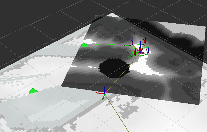
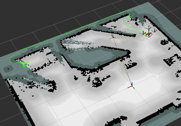
These measurements are used by SLAM Toolbox to construct and update an occupancy grid map while estimating the robot’s position.
The laser scans are also used by Nav2 for obstacle detection, path planning, and collision avoidance.
Unlike the downward-facing ToF sensors, the LiDAR primarily observes obstacles within a horizontal scanning plane. It cannot reliably detect drop-offs below that plane, which is why the additional cliff detection system is necessary.
Battery
For ease of use, a 5000 mAh NiMH battery with a nominal voltage of 7.2 V is used instead of a lithium battery.
Motors
The crawler is powered by two Greartisan 12 V DC geared motors with a rated output speed of 100 RPM. Each motor features a 37 mm diameter reduction gearbox with an eccentric output shaft.
The integrated reduction gearbox reduces the motor’s rotational speed while increasing the available output torque.
Two HW-039 motor driver modules are used to control the left and right motors independently. For forward motion, the two hardware PWM channels of the Raspberry Pi are used to control the motor speeds. Reverse motion is controlled using software-generated PWM signals on separate GPIO pins.
The GPIO assignments are as follows:
| Motor | Forward (Hardware PWM) | Reverse (Software PWM) |
|---|---|---|
| Left | GPIO 12 | GPIO 16 |
| Right | GPIO 13 | GPIO 26 |
Software Architecture
The Crawler runs ROS 2 Jazzy on both its onboard Raspberry Pi and a remote virtual machine hosted on a Proxmox server.
This distributed architecture separates hardware-dependent, low-level control from more computationally demanding mapping, navigation, and exploration tasks.
Onboard Software
The Raspberry Pi 4B executes hardware-related ROS 2 nodes, including sensor drivers, wheel odometry, motor control, teleoperation, and cliff detection.
A dedicated velocity control node processes velocity commands received through the ROS 2 command velocity interface. It converts the requested linear and angular velocities into appropriate motor control signals.
The onboard software also implements safety-related functions, including the detection of cliffs and emergency recovery behavior.
Server-Side Software
The computationally intensive navigation and exploration components run on a Debian-based virtual machine hosted by Proxmox.
The main components are:
- SLAM Toolbox: Simultaneous localization and mapping using LiDAR scans and odometry. It constructs a map of the environment while estimating the Crawler’s position.
- Nav2: Autonomous navigation, including global path planning, local trajectory control, obstacle avoidance, costmap management, and recovery behaviors.
- Frontier Explorer: Autonomous exploration of previously unmapped environments using the open-source frontier_exploration_ros2 package.
Frontier exploration identifies boundaries between known free space and unexplored regions of the map. It selects exploration targets and sends navigation goals to Nav2, allowing the Crawler to progressively map previously unknown environments.
Custom costmap and keepout-mask nodes integrate detected cliffs into the navigation system. This prevents the path planner from treating dangerous terrain as freely traversable space.
Communication
Communication: Wi-Fi (2.4 GHz), ROS 2 with Cyclone DDS.
The onboard Raspberry Pi and the remote ROS 2 server communicate over Wi-Fi using the Cyclone DDS implementation of the Data Distribution Service (DDS).
Both computers operate within the same ROS domain, allowing distributed ROS 2 nodes to exchange sensor data, odometry, transforms, navigation goals, and velocity commands.
This architecture makes it possible to run computationally demanding algorithms on the server while keeping hardware interfaces and essential safety functions onboard the Crawler.
ROS2 Structure
Impressions